HOW-TO: Create Colour Profile for Your Camera

This is a description on how to perform colour calibration of a camera and a specific photo shoot settings under Linux using the UFRaw RAW format handler and the Argyll Color Management System. This probably works under Windows or OsX as well, but it is untested.

Color Calibration Examples
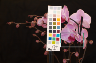
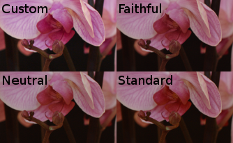
Figure 1: Color Calibration Examples.

After struggling with LPROF and failing to make it work for me (see this how-to), I've reworked my work flow for colour management to incorporate Argyll Color Management System instead. In a related how-to I described how to use the ICC profiles that come with Canon Digital SLR (EOS) together with UFRaw to digitally develop colour calibrated photographs. This how-to describes how you can use the Argyll Color Management System to create your own ICC profile that describes the lighting conditions of a photo session. This profile is then used to develop the RAW photos from your camera with correct colours and brightness.

In figure 1 there is a photograph with the QPCard201 used to calibrate the colours. This is the target, i.e. colour calibration chart, that I've been using and which will be used as an example in this how-to. There is also a set of close-up images showing the results from using the custom profile from this how-to compared to some general profiles that came with the camera. The general profiles required manual white balancing and exposure adjustments to get this close to the custom profile.

ChartMarker
Figure 2: ChartMarker screendump.
(see also video @ YouTube)

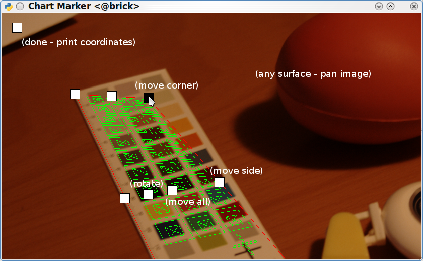
In photography, as opposed to when calibrating a scanner, you will need to manually mark the corners of the target in the picture. This is because the Argyll tool for extracting colour information from the image can detect the orientation of the target only if it is facing the camera, like it would in a scanner. For this I use my own GUI which is shown in figure 2. The usage is straightforward — execute the script without any arguments for a list of command line arguments and click on the screendump for usage information of the actual GUI.

In my work flow I use

To put this together I used the following resources

See also:

Preparations

  1. Install UFRaw, Argyll and ImageMagick. I did this with APT since I run Ubuntu.
  2. I saw that the latest version of Argyll had a target template (CHT) for QPcard201, but it doesn't fit my card. It might be that it was generated from the reference image from qpcards web page which seems to be a computer generated image and not a picture of the real thing. If you have a QPcard201 you could try mine, qpcard201.cht. You'll also need the CIE file (with the colour values), qpcard201.cie.
  3. Download UFRaw settings suitable for generating the profile and using the profile, .ufrawrc.make_profile and .ufrawrc.use_profile, and put them in ~/ (since you already have your .ufrawrc file there).

Work Flow

  1. Start you photo shoot by taking a picture of your colour chart (target).
  2. Convert your RAW image file depicting the target to PNG format using UFRaw and the "make_profile" configuration file. The configuration file sets 5000 K white balance and disables colour profiles for linear conversion. UFRaw can export directly to TIFF, but the TIFF file became corrupt on my current installation. ufraw-batch --conf=$HOME/.ufrawrc.make_profile myimage.cr2 \ --out-type=png --output=/tmp/custom_profile.png
  3. Convert the PNG file to TIFF. If your installation of UFRaw makes good TIFF files, then you can skip this step. convert /tmp/custom_profile.png /tmp/custom_profile.tiff
  4. Identify the coordinates for the "fiducial square" in your target. This is typically its borders. I've implemented a GUI facilitating this process, the target matching GUI. It's a bit of a hack but works well for me. ChartMarker.py -s 0.5 -a -t <CHT file> \ /tmp/custom_profile.tiff The parameters are: -s, scale the image, -a, show sample box areas, and -t, target template.
  5. Use scanin to extract the colour values from the chart in the image. The following line works for me and gives a nice diagnostics image. scanin -dioa -F <fiducial coordinates> \ /tmp/custom_profile.tiff <CHT file> <CIE file> The parameters are: -dioa, create diagnostics image with image (i), sample box outlines (o) and sample box areas (a), -F, coordinates for the fiducial square.
  6. Now check the diagnostic image (diag.tif) to make sure that the coordinates and target template were correct and that the sample box areas are all inside the colour patches. display diag.tif This should not be necessary if you used ChartMarker with the -a and -t flags. In that case you can also remove the -dioa flag from scanin.
  7. If everything went alright so far you're ready to generate a profile from the measure data that you extracted in the previous step. This is done using colprof colprof -ag -qu -bn -y /tmp/custom_profile The parameters are: -ag, gamma+matrix algorithm type, -qu, ultra high quality, -bn, only A2B table (since it's an input device), and -y, verify the A2B profile.
  8. Finally just clean up all temporary files. mv /tmp/custom_profile.icc /tmp/custom.icc rm /tmp/custom_profile.*
  9. Finally you may open your other RAW images from the same photo shoot using UFRaw with the "use_profile" configuration file. ufraw --conf=$HOME/.ufrawrc.use_profile myimage.cr2
  10. Since you'll follow this workflow many times, make one script for generating a profile and another to do batch photo development using the profile. Use your favourite file browser (I use Dolphin) and associate the two scripts with your RAW file format.